As part of the Fritzes Best Interfaces award for 2026, I am reviewing the interfaces in Star Trek: Section 31. This post is about the interfaces used by Fuzz.

Fuzz is a Nanokin, a species of microscopic, squidlike beings with impressive, tiny spaceships. To engage with his teammates in the human-scale world, he does so by flying into a black-market android built to look like a Vulcan, and controlling it from within. In the film they call both the android and the Nanokin “Fuzz”, but that would get confusing in writing, so I’ll call the android the Vulcanbot. I want to believe that the character concept began as a tardigrade or amoeba, but it got more octopus-like over development. From its tiny spaceship, it can get through tiny holes and cracks in machinery or body modifications, hook in, and cause plot-critical mischief.


When the camera is at the nano-scale, the film uses tilt-shift and floating-particle techniques to emphasize the smallness of Fuzz. That means that only a small strip of things are in focus in any given shot, giving us less visual information to work with than usual. So though I’ll cover it, know I’m working with a lot less than I might ordinarily have.
Nanoship
The ship he flies around in is roughly spherical, and about ten times his own diameter. It kind of looks like him, which is both a funny and philosophical design choice. Its surface ripples in waves similar to the surface of the unnamed Section 31 ship that Sahar pilots above the safehouse planet. I think the implication is that it is made from programmable matter.


It has retractable, tentacle-like appendages coming out from the hull. They can be extended to surfaces to hold the ship in place and interface with electronics. I counted 20 tentacles in one screen shot, but if they’re programmable matter, they can be made ad hoc.
The interaction design question is how these are controlled, but, with programmable matter, general artificial intelligence, and agents all part of the novum stack for the movie, it might be as simple as a prompt: “When you are near safe access points, create connectors to them.” Since it’s never shown in the film, though, we have to leave it as a guess. I leave it as an exercise for the reader to imagine how it might work with a modern technology stack.


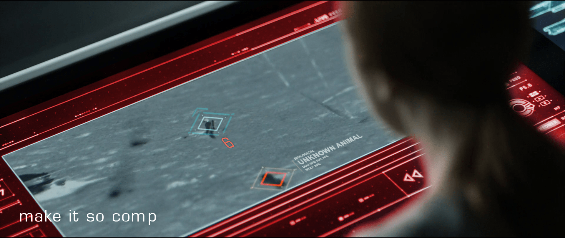
There is a curved viewport at the front of the ship, subtending around 120° from the pilot’s view. Additional displays to the left and right of the viewport extend the display surface to around 180° degrees. The viewport features an augmented, highly dynamic display, able to show live video, star charts, big red labels, waveforms of audio—whatever is needed in the moment. Language in the display is both English and Nanokinese (for lack of an official known name of that script in the lower left). Stylistically it has a cyan border with white contents, with dusty lavender highlights. Semi-randomly-wandering line segments appear throughout. Sadly, we do not see Fuzz futzing about with this interface at all, so we cannot evaluate that part of it. But it is the context of both the nanomap and nanolever, discussed below.
Nanomap
A curious element in the center of the volumetric projection console is that of an edge-lit, standing human figure with a transverse ring around the waist. It is always there and does not appear to change throughout the film, regardless of the position of the body he’s in or controlling. It might serve simply as a map of the current body-in-question for alert and display purposes. Stuff like wayfinding or a damage control diagram.

We don’t see it when Fuzz is in Zeph or Dada Noe, but it would be cool if we saw it change to match the current host. Even cooler if we saw some vague indication of the surroundings around the host. Even coolest if we’d seen one virtual body for Vulcanbot and a second one for Zeph on the dashboard when Fuzz had the ability to remote control both.
Nanolever
When Fuzz’ deception is figured out by Georgiou and his Vulcanbot is face-to-face with a phaser, Fuzz grabs a lever and pulls it toward himself. In response Zeph’s corpse—controlled by his mechsuit—begins to rise, again under the control of Fuzz.
The lever is interesting for two reasons.
First, it’s the only physical control visible we see in the ship. (Fuzz has his tentacles raised above the viewport in a number of scenes, but the shot is from the outside of the ship, so we don’t know if he’s operating controls or just bracing himself.) A physical control is persistent and can’t get lost in occluding windows of a digital display. This tells me that Fuzz knew he might get exposed, and might need to pull the lever at any moment to initiate his ace-in-the-hole plan. The physical lever facilitated that much better than a digital one would.

Second, look at the physical design. It is textured and curved. These are both features which make it easier for octopus arms to grasp and manipulate. (I’m not a cephalopod expert, but this study says so.) We don’t know if Fuzz’ tentacles function similarly to octopus arms, but it’s a reasonable place to start.
I have less confidence in the two rings at the top of it. A shopping search for “lever controls” shows that none of them feature rings or holes. I’m not an industrial designer, but having those rings seems error prone. Not to grip, but to release. If your fingers or tentacles are in those rings, and some emergency situation requires you to quickly grab something else, you might be critically delayed by the fine motor control required to withdraw from the rings. If the lever is just a stick, releasing is practically a non-issue. So I’m less fond of the rings. If you can think of a good reason for these, let me know in the comments.
An Agent!
Since I started thinking in-depth about agentive technology, I’ve been noting when I see them in sci-fi. It’s rare. Up until Fuzz, Dr. Strange’s Cloak of Levitation has been my go-to example. Literacy in agents is becoming more important over time, and popular media is one way that people learn about it. (Especially its risks.) I was delighted to see a plot-centric use of them in this film.

Vulcanbot is an agent while Fuzz is in Zeph, and then Zeph-corpse is an agent as Fuzz is fighting Georgiou to escape. Vulcanbot even handles the b-plot battle with Sahar before being caught in the climactic explosion.

This literacy of what an agent is and what it’s capable of is critical to the protagonists’ fates. If Georgiou hadn’t sussed it out, the team might have split up from unresolved suspicion. Fuzz would have snuck away and San would have returned with the Godsend to the Terran Empire and used it to return and conquer Prime. So her agent-literacy saved the day.
The central role this agent played in the film is one reason I really loved it. Of course even more interesting would have been to see how Fuzz expressed his commands for the agents and monitored their performance against those goals, but because this needed to be hidden for the Big Reveal, we don’t get to.
A missing signal
One important feature that is only weakly implemented in the Vulcanbot and should be stronger when we implement similar technologies in the real world: Agent-mode signals. These signals would convey to observers whether the technology is being operated by a human sentience or when it is being driven by agentive software.

Of course Fuzz is deeply vested in deception. Vulcanbot acts a little strangely when in agent mode, but it’s because the AI is not rich enough to mimic Fuzz on autopilot. It’s easy to imagine that if it could have been a perfect mimic, Fuzz would rather that.
But for us in the real world we want to know what we’re dealing with. It changes how we interact and what our expectations are. I argued for these deliberate design interventions in the context of Google Duplex way back in 2018, just not on this blog. So let me assert them here. A more ethical Vulcanbot would shift to a modulated voice as a hot signal when it was operating agentively, and interject a cold signal when circumstances called for it.
Delicious woke
Star Trek has addressed queerness before. I’m glad to see it again, considering how the weird MAGA Trump-suckup regime is trying to villainize and scapegoat trans people like the Nazis did with Jewish people here in my home country. And, to be clear, fuck that nonsense.
Though there’s a diegetic “excuse” as to why it is, the perceptual truth is there’s something invisible inside a character that has us accepting a masculine version for most of the movie, and then accepting a feminine version at the end. Same body, different behaviors, sci-fi reason.

The rationale is there, so the queer-o-phobes don’t have a good excuse to reject it outright. Diegetically, the invisible part is binarily gendered. Diegetically, that’s what informs the Vulcanbot’s outward behavior, not *gasp* actual genderqueer-ness. It’s fantastically designed for the right kinds of cognitive dissonance.
Perfect for Pride Month. Maybe we can have Nanokin as a teeny tiny marshal for the next sci-fi Pride Parade.

Nice going, team Fuzz, and happy Pride month!
Next up: The quadrant-destroying weapon commissioned by Georgiou